Miscellaneous improvements to my network segmentation setup
Refresher & motivation
After a long and honestly unplanned break, I am back to writing again. The good news is that, I have not been sitting idle for the last year, and there are a few projects I have worked on which I will be covering in the next few articles.
With that disclaimer out of the way, I would like to start with the first project I got busy with, which has to deal with my home network architecture. As a reminder, where we left things last time, I had managed to re-purpose a
Reorganizing the network
In Figure 1, I have reproduced the architecture of the network as last configured in the previous article in this series. 
The first thing that I wanted to change about my network was the position of the Pi-Hole in the network. Specifically, I wanted it to be connected the to the OpenWRT router, instead of the ISP router. I wanted to do this for the following two reasons:
- My ISP’s router’s Ethernet ports are all 1Gbps, having one of these ports being taken by a DNS server, knowing its traffic will never saturate its maximum bandwidth seemed too wasteful. This seemed especially wasteful knowing that the OpenWRT router I had, still had one additional free 100Mbps port.
- I thought having all my “experimental” stuff behind the OpenWRT router made for a more tidy setup. Come to think of it, this could actually even present a slight performance gain: Having the DNS requests from my TV be confined behind the OpenWRT router means less packets for my ISP’s router to handle. Knowing how anemic my ISP’s router is, this performance gain might actually be worth it.
Making this first change to my network architecture was quite straight-forward. I chose to move the Pi-Hole to the LAN network (green highlight in Figure 1), and assign it IP address 192.168.1.2. Following this change, OpenWRT needs to be configured to use the new address as the DNS server used for the LAN and TV_LAN networks. Similarly to how we configured it initially in a the previous article in this series, we need to set the “Use custom DNS servers” setting to the new value 192.168.1.2 in both the LAN and TV_LAN configuration menus.
Adapting the routing settings
Previously, I had setup a few of my other devices connected directly to my ISP’s router to use Pi-Hole as their DNS server. Because my ISP’s router does not even give me the option to configure a DNS for my local network, I had to configure the DNS address on each of these devices separately. This was straight-forward because the Pi-Hole was in the same local network as these devices (192.168.0.0/24). Having now moved the Pi-Hole behind the OpenWRT router and into a different sub-net, I now additionally need to add a route to the Pi-Hole for each one of these devices (My ISP’s router also does not give me the option to set routing tables). The required configuration is as follows:
1
2
3
4
5
6
7
DNS Server: 192.168.1.2

Routing table:
 Address     |  Netmask      |  Gateway    | Metric
-------------|---------------|-------------|-------
 192.168.1.0 | 255.255.255.0 | 192.168.0.2 | 101
 192.168.2.0 | 255.255.255.0 | 192.168.0.2 | 101
The Routing table above now allows to forward traffic destined to the LAN 192.168.1.0/24 and TV 192.168.2.0/24 subnets to the OpenWRT router (IP Address 192.168.0.2). This would be useful to reach both these subnets, and is frankly something I could have done when I first configured my OpenWRT network. However, I hadn’t done it until now because I had no devices connected to either LAN or TV_LAN networks which I wanted to reach from my other devices.
Adapting the firewall settings
Previously we had configured the default firewall policy on OpenWRT for incoming traffic on the WAN interface to be REJECT. This means that traffic that is emanating from devices connected to my ISP’s router and destined to the Pi-Hole will be filtered out by OpenWRT. Such traffic would include the DNS requests sent by these devices to the Pi-Hole. In order to change this, we need to add the following firewall rule to OpenWRT:
 Figure 2: Allowing access to Pi-Hole’s DNS
Additionally, we need to allow access to Pi-Hole’s web-interface and SSH server which are required for management and software updates. Because I plan to connect more devices which I would also access through SSH to the LAN network, I thought it would be easier to simply allow all SSH traffic from the WAN interface to the LAN interface, instead of creating a separate rule for each device (even though that is the more secure approach). The firewall rules to achieve this are as follows:
 Figure 3: Allowing SSH and Web access to LAN network
Plugging in more devices for more fun
As hinted at in the previous section, with my setup slowly maturing, I thought I would start plugging more devices behind the OpenWRT router to give me the opportunity to try more fun stuff in the future. Specifically, because I wanted to connect an additional TV which was far away from the OpenWRT router to the TV_LAN, I added a wireless Access Point downstream from the OpenWRT router. The AP also provides four Ethernet ports, so I connected my original TV to one of those . This was in order to spare my limited OpenWRT router ports, and not have to use an additional switch in my architecture. Additionally, I connected an old laptop with a fresh installation of Ubuntu server to the LANnetwork, using the last available port on the OpenWRT router, and assigned it the static IP address 192.168.1.3. The architecture of my network is presented below:

Improving DNS requests transparency
Looking into Pi-Hole graphs
I have been using Pi-Hole for two years now, and I am generally happy with its performance. I particularly like all the graphs and charts made available through its Web UI. Below is one of these charts, showcasing a summary of the DNS queries it handled while deployed in my network (and used mainly by my TVs and a couple other devices):
 Figure 5: Summary of DNS queries handled by Pi-Hole on my network
As you can see, almost 64% of the DNS requests received by Pi-Hole are denied. At first sight, this is quite a high filtering rate. However, this is probably due to my TV attempting to connect to a specific server which is blacklisted by Pi-Hole, and repeatedly sending DNS requests for this domain.
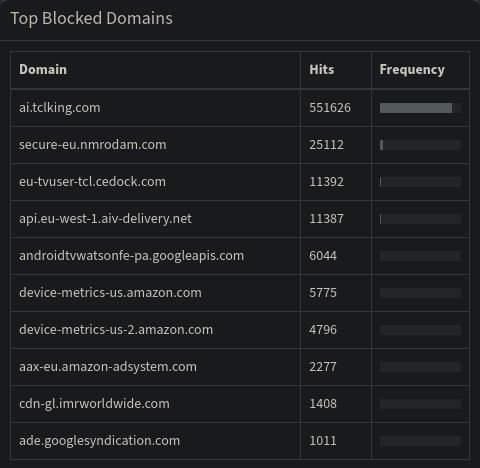 Figure 6: Top blocked domains by Pi-Hole on my network
Looking into the list of top blocked domains by the Pi-Hole shown in Figure 6, seems to confirm this. In fact, almost 89% of all DNS requests blocked by Pi-Hole are for a single network: ai.tclking.com. TCL is my TV’s manufacturer, I tried looking into what this URL leads to, but all I could gather was that it has something to do with Amazon’s Alexa. I don’t use Alexa, and I have disabled the microphone on my TV when I first turned it on (both using a dedicated hardware button, and in the software settings). I am not sure how much I can trust that the TV’s microphone is actually off, so having the DNS requests being filtered is a good additional measure to have I guess. The constant DNS requests are evidently not optimal, and are probably costing me some degree of performance on my TV. A more optimal solution would be to white-list this URL in Pi-Hole, and then block any traffic to the resolved IP address. However, it might well be that the TV would then keep pinging that IP address, thus bringing me back to square one. To be honest this is something I have not researched enough, but it would definitely be worthwhile to look into.
Limited transparency issue
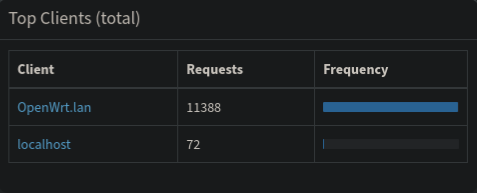 Figure 7: Breakdown of DNS requests by client
Pi-Hole also offers a breakdown of the logged DNS requests by client. Figure 7 shows how this graph originally looked on my network. As you can see, the graph does not reveal much. All the requests received by Pi-Hole seem to be emanating from the OpenWRT router instead of the actual clients. This is actually due to the way we have previously configured the LAN and TV_LAN networks. The “Use custom DNS servers” setting does not inform the clients connected to the network of which DNS server to address their requests to, rather it configures the server which OpenWRT itself will use to resolve requests received from clients connected to the network. The only DNS server the clients know about is the OpenWRT router itself. This explains why the Pi-Hole graphs only show the OpenWRT router as a client: all DNS requests received by Pi-Hole were effectively sent by OpenWRT. Alright, now that we know the problem, how do we solve it?
DHCP option 6 to the rescue
As it turns out, there is a very simple fix to this. The DHCP protocol provisions for different options to be communicated to the clients by the server in the DHCPOFFER message1. One of the available options allows the server to communicate the DNS server to be used by the clients. This is option 6 2. So in order to make our clients communicate their DNS requests directly to the Pi-Hole instead of the OpenWRT router, all we need to do is configure the OpenWRT DHCP server to use option 6 with a value of 192.168.1.2 (IP address of Pi-Hole) for the LAN and TV_LAN networks. In OpenWRT’s Web UI the option can be found under menu Interfaces > [interface_name] > DHCP Server > Advanced Settings. In the DHCP-Options input box, the option needs to be given with the format: 6,192.168.1.2
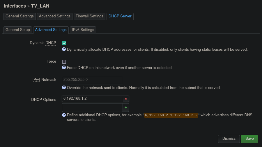 Figure 8: DHCP option 6 setting in OpenWRT’s Web UI
Updating the firewall rules
Setting the Pi-Hole as the DNS server in the DHCP is only half of the equation. If you remember, we had previously configured our OpenWRT firewall to reject all traffic emanating from the TV_LAN network and destined to any local IP address (192.168.0.0/16). In order for the DNS requests from the TV_LAN to reach Pi-Hole, we need to add a firewall rule whitelisting such request. Additionally, we need to make sure this rule is positioned in the firewall table above the rule rejecting all traffic targeted toward local addresses. Figure 9 shows these two rules.
 Figure 9: Firewall rules denying all local traffic from TV network other than DNS requests to Pi-Hole
Taking a look at the improved logs
Now that we have configured Pi-Hole to be used as a DNS by our clients, and allowed DNS traffic from these clients to the Pi-Hole, we can finally take a look at the logs.
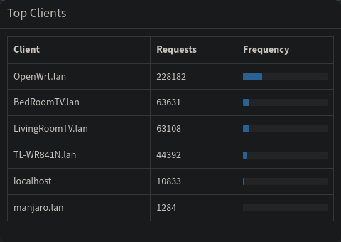 Figure 10: Breakdown of DNS requests by client (fixed)
Figure 10 shows the list of clients gathered by Pi-Hole after I let my network run for some time in order to allow for new logs (if it weren’t clear, there is no way of fixing the logs which had been captured before our modifications). As can be seen, Pi-Hole now receives the requests directly from the different clients, the resulting logs now give a much better insight into the network. In addition to the graphs I have been showing this far, Pi-Hole also makes real-time logs available, and now those two are assigned to the correct clients. I found this (now correct) real time logging to be a very useful tool when attempting to debug different issues on my network.
Improved DNS filtering with DNS requests hijacking
The Pi-Hole filtering approach relies on the fundamental assumption that the clients will use the Pi-Hole as their DNS server. For the majority of devices connected to my network, this assumption is true. This is because most devices either use their default gateway as their DNS server (i.e. the router they are connected to), or use whichever server advertised by the DHCP server present on their network (through DHCP option 6, as is the case now in my network). However, as it turns out, some devices and applications are delivered with hardcoded DNS server addresses. This is the case for some android devices, and of the Amazon Prime application running on my Smart TV. I had noticed this behavior when I once tried to block all outgoing traffic on port 53, except that meant for the Pi-Hole. This resulted in the Amazon Prime application on my smart TV failing to start.
Similar to the other problems I previously faced on my network, the solution to this one lays in more firewall rules. Specifically, we need to detect all traffic coming from the TV_LAN with a destination port of 53. The destination IP for all packets of this traffic will then need to be changed to that of the Pi-Hole. Unlike all the firewall rules we have established so far, the rule we require now is too complicated for OpenWRT’s Firewall Web interface. Thankfully, OpenWRT allows for a fully manual configuration of Firewall rules through a text field in which, iptables commands can be given. This field is available under Network > Firewall > Custom Rules.
iptables is a user interface which makes it possible to configure the Linux Kernel’s Netfilter packet filtering framework3. When I first started looking into this issue I was not familiar enough with iptables. I had used it before to configure some VPN rules, but that was just by reusing some rules I had found online, and which I only half-understood. Thankfully, looking around online I found other people who had faced the same issue as I, and who had come up with iptable rules that only needed some slight modification to solve my problem4. Below are the iptables rules I added to my configuration:
1
2
3
4
5
6
7
8
9
# Pi-Hole Hijack
# Section 1: Log and redirect DNS Traffic
iptables -t nat -N piholehijack
iptables -t nat -I piholehijack -j LOG --log-prefix "Pi-Hole Hijack"
iptables -t nat -A piholehijack -j DNAT --to-destination 192.168.1.2

# Section 2: Anything else is hijacked
iptables -t nat -A prerouting_TV_rule -p tcp --dport 53 -j piholehijack
iptables -t nat -A prerouting_TV_rule -p udp --dport 53 -j piholehijack
Since I first found these rules, I have gained a better understanding of iptables and am now in a better situation to explain what each section of these rules does:
- Section 1: Here we create a chain within the NAT table. We are giving the name “piholehijack” to this new chain (line 3). We then configure a first rule for the newly created chain, specifically, we configure
iptablesto add the prefix “Pi-Hole Hijack” to each line of the logs created for packets filtered through this chain (line 4). This is simply to give packets affected by this chain better visibility in theiptableslogs. Finally, we add the rule which implements the logic we want: for all packets going through this chain, change the destination IP to that of the Pi-Hole (line 5). - Section 2: In the previous step, we created a new chain, and configured it to overwrite the destination address to that of the Pi-Hole. However, on its own, this chain and rule are ineffective because there is no traffic going through the chain. As such, in this step, we add rules to the already existing chain “prerouting_TV_rule” in order to redirect some of its traffic to the “piholehijack” chain. The “prerouting_TV_rule” rule was automatically created by OpenWRT when we create the
TVnetwork and firewall zone (back in part 2 of this series). All traffic coming out of theTVnetwork is fed into this chain, so by applying a rule here which filters only DNS traffic and feeds it into the “piholehijack” chain, we can be sure that such traffic will be re-routed towards the Pi-Hole (thanks to the rules from the previous step). The way to filter only DNS traffic is through filtering TCP and UDP traffic destined towards port 53. This is what the rules in lines 8 and 9 respectively specify.
The original post4 where this solution was proposed also included a third section in which masquerading is performed for all traffic routed into the LAN network and destined towards the Pi-Hole. I am including this section below.
1
2
3
# Section 3: fix "reply from unexpected source"
iptables -t nat -A postrouting_LAN_rule -d 192.168.1.2 -p tcp -m tcp --dport 53 -m comment --comment "!fw3: DNS Pi-hole MASQUERADE" -j MASQUERADE
iptables -t nat -A postrouting_LAN_rule -d 192.168.1.2 -p udp -m udp --dport 53 -m comment --comment "!fw3: DNS Pi-hole MASQUERADE" -j MASQUERADE
Masquerading is also referred to as NAT (Network Address Translation), and more precisely as S-NAT (Source NAT) in contrast to D-NAT (Destination NAT). It refers to an operation performed by a router, in which it modifies the source address of a packet it is routing, and (usually) overwrites it with its own. This is predominantly done by routers that operate as a gateway between a private network and a public one (because private IP addresses cannot be routed in the public Internet).
In this scenario, the masquerading was added to avoid having a private address (Pi-Hole’s) reply to a request originally intended for a public address (the DNS server for which the request was originally intended). From my understanding OpenWRT might complain in such a scenario, and raise “reply from unexpected source” errors. In my case, I did not see this error, and the first two sections were enough for successfully rerouting DNS requests. Furthermore, adding this section would mean that all requests rerouted to the Pi-Hole, would end up with OpenWRT’s own IP as a source address, thus rendering our efforts to improve the Pi-Hole’s logs transparency moot.
I am unsure if my understanding here is completely correct, but my setup seems to be working for the time. In the future, I would like to revisit this section, once I have a better understanding of iptables.
Interesting tangent: Why is masquerading needed?
Spending time going through the firewall rules from the previous section made me realize something. To help clarify my realization, I have reproduced the Firewall policies section of OpenWRT’s web UI in Figure 11. One thing that perplexed me at this point, was the enabled Masquerading option for the WAN interface. As touched upon briefly in the previous section, Masquerading is used in most cases by routers which sit at the periphery of a private network, and route traffic towards the public Internet. This Masquerading is required because the IP addresses used within private networks (as defined in RFC19185) are not allowed in the public Internet. As such, packets containing these IP addresses will be automatically rejected by routers on the Internet. Masquerading consists on the router overwriting these addresses by its own (as they are leaving the private network), and maintaining a table to keep track of what client sent which request, once the responses are received.
 Figure 11: Default policies for the different Firewall zones
Following the previous explanation, and considering that my OpenWRT router is downstream from my ISP’s router (see Figure 1), it should follow that Masquerading is not needed. This ought to be the case since OpenWRT’s “WAN” is network 192.168.0.0/24 as configured on my ISP’s router. For this reason, I attempted to disable the Masquerading. However, surprisingly enough, doing this caused traffic downstream of OpenWRT to stop working: Requests were being sent (by Pi-Hole, the TV, and other clients), but no replies would come back. This issue would stop as soon as Masquerading was turned back on.
It took me a lot of online research before realizing what the issue was. Figure 12 and Figure 13 respectively showcase the flow of a request sent from a device downstream of the OpenWRT when Masquerading is disabled and when it is enabled. The network configuration is the same as has been the case throughout this article: OpenWRT’s LAN is configured to have a range of 192.168.1.0/24 whereas the ISP’s router is configured with a network of 192.168.0.0/24 In both scenarios, the IP address of the client performing the request is 192.168.1.3.
In Figure 12 Masquerading on OpenWRT is disabled. In this case, the source IP field of the request is not modified by OpenWRT when it forwards it to the ISP router. The ISP router then forwards the request towards the Internet, and performs NAT-ing while doing so (However, that is irrelevant to us in this context). The issues start when the response is received by the ISP router which then needs to transmit it back to the laptop at 192.168.1.3. The ISP router does not know that network range 192.168.1.0/24 is reachable through the OpenWRT router, as such it drops the packet.
Usually, it should be possible to inform the ISP router of this, by simply adding a row to its routing table. However, as I have covered previously, the software of my Router is so limited, it doesn’t even allow for this.
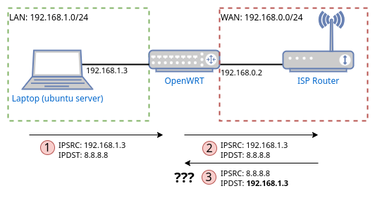 Figure 12: Flow of a request/reply without Masquerading on OpenWRT
In Figure 13, Masquerading is enabled on OpenWRT, meaning that before OpenWRT forwards the request to the ISP router, it overwrites the source IP with its own (192.168.0.2). As such, when the ISP router later receives the reply, it will be addressed to OpenWRT. The ISP router knows this IP address is to be found on its own network, and forwards the packet to OpenWRT. OpenWRT in its turn performs the reverse operation it did when it forwarded the request, and overwrites the destination IP of the reply with the original source IP address (192.168.1.3). When it is time to forward the reply, OpenWRT can see that the destination IP is within its network (192.168.1.0/24) and forwards the reply to the laptop.
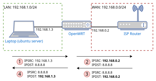 Figure 13: Flow of a request/reply with Masquerading on OpenWRT
Although I was aware of what Masquerading was, it did not occur to me that it would find a use also within a private network. When I initially set up my OpenWRT router behind my ISP router, I remember quickly reading about some possible issues whenever one configures one router behind another (such issues include double NAT-ing). This scenario never occurred to me as a possibility, but I am really glad I came across it.
Looking towards the future
Through the aspects covered in this article, I have managed to further improve my simple network architecture. As a reminder, all of this was achieved using old/reused hardware which was just collecting dust (old Fritz!Box router, old laptop, and old RaspberryPi). Although I am very satisfied with what I managed to achieve with such simple hardware, I am starting to see its limitations. In particular, the limited number of ports on the Fritz!Box and their limited bandwidth (100Mbps) are limiting the number of devices I can connect downstream of OpenWRT. Additionally, having one router downstream of another with both performing NAT, has caused me some issues already, and is bound to cause more in the future.
Finally, I did not cover it in this article, but during the two years I have been using OpenWRT new versions have been released. The new version introduces a switch to a new software architecture (DSA) that is incompatible with the one used by the version of OpenWRT I am currently using (swconfig). The consequence of this is that my configuration is not automatically transferable through the upgrade, meaning that upgrading would probably require me to start configuring my OpenWRT router from scratch. For all these reasons, I have been considering upgrading to a more capable hardware/software stack. This will hopefully be the topic of the next article in this series. Until then!