Laying the groundwork for my Homelab with OPNSense
Motivation
In the previous two-part series regarding my Vodafone cable-internet equipment, I have shown how one can switch the Vodafone Station into bridge mode (in order to deactivate all but its modem functionality), and how one can replace the Station with a third-party modem all-together. Following either of these guides would leave you with a modem which is only capable of forwarding a single IP address (assigned to you by your ISP) to whichever device is connected to it. Seeing as I have more than one device at home that I would like to connect to the internet, I would need a router downstream from my modem, which would allow me to create a local network with its own IP range. Devices connected downstream of the router will then each receive an IP address and their traffic will be routed according to the router’s configuration.
In this article I would like to cover my choices for the hardware and software to use for my router. I would also like to present the new architecture I have adopted for my network.
The software: OPNSense
In contrast to previous choices I had to make where I spent a lot of time comparing multiple possible candidates before settling on one, I knew from the get-go that I wanted to make use of OPNSense. Similarly to VFIO, I was originally introduced to the existence of free and open-source firewall/router software utilities through one of Level1Techs’ videos. If you watch the video you might notice that the software being referenced there is actually pfSense and not OPNSense. OPNsense is actually a fork of pfSense1 which itself is a fork of the now discontinued m0n0wall project. All three utilities are based on the FreeBSD operating system. I chose to go with OPNSense instead of pfSense for multiple reasons:
- OPNSense is recommended by the developer of m0n0wall2.
- OPNSense seemed to me to be the more actively developed project.
- The community around OPNsense gave me the impression of being more open and helpful towards non-conventional deployments, namely when OPNSense was installed on non-conventional hardware and using exotic network cards.
The last two points are completely subjective, so if you are interested in trying pfSense instead of OPNSense, by all means don’t let my own possibly-mistaken impression hold you from that.
OPNSense boasts quite the roaster of features3, most relevant among those for me were the following:
- 802.1Q VLAN support and Stateful Firewalls: Which would allow me to reproduce the network segregation I had previously implemented for my IoT devices.
- VPN support: Both as a server and a client with support for IPSec, OpenVPN, and Wireguard.
- Intrusion detection and prevention systems.
- A comprehensive catalog of plugins.
- Simple configuration backup & restore mechanism.
- Weekly security updates with a twice-a-year releasing strategy.
All of these features are made even more accessible thanks to a very elegant UI which also enables easy reporting and monitoring. Finally, the project boasts and exhaustive online documentation and rich community which would make future debugging hopefully not too much of a headache.
The hardware: Router, Switch, and Access-points
Router
The great thing about OPNSense is that it still is based on x86-64 FreeBSD, meaning one can install it on any generic 64-bit consumer-machine. This translates to a wide range of possibilities starting from single-board-computers and old laptops, all the way to miniPCs and full tower desktops. However, realistically, and in a home-setup one would not want to attempt to use OPNSense on such non-purpose-built devices.
The main road-blocker when reusing such generic devices is a router being by definition operated between at least two networks, and as such requiring at least two Network Interface Cards (NICs). Consumer devices on the other hand, are usually configured with a single Network Interface Card (NIC). There are some workarounds to this limitation, as an example, one can use a USB-to-RJ45 adapters to attach additional NICs to a laptop. However, such exotic setups end up being unstable, and causing issues down the road (in the example of the USB adapter, the NIC is attached downstream of a USB controller which can cause a downgrade in performance). When using a more performant machine, such as a tower desktop or even a mini-desktop, one can always attach additional NICs using PCIe expansion slots. The downside there is that the increase in performance of these machines comes at the price of a power consumption an order of magnitude higher than a traditional router. Considering the machine will be in operation 24/7, that will incur significantly higher energy costs, which would not be justifiable in a home-setup. For these reasons, it is much more recommended to make use of something halfway between the two extremes discussed above. Thankfully, there exists a very wide range of options in this Goldilocks zone.
The search keyword to use is “Firewall appliance” (well, I guess that makes them two words). These are mini-PCs that are purposely built to act (as the name hints) as firewalls between different networks. In this context, I find the term firewall to be confusing, since in our (and most) deployment scenarios the device will also assume the very important role of a router.
In order to assume their role, these appliances are equipped with at least two NICs (usually four, sometimes more). They are usually equipped with multi-core (though lower-end) processors, which allows for silent operation without the need for additional cooling (depending on the number of ports and bandwidth the device is advertised to have). These processors are nonetheless more than capable of performing the routing, packet filtering, and encryption tasks these appliances would be expected to perform during their operation (think Intel Celeron instead of AMD Ryzen). An example of such an appliance, and the one I ended up choosing for my setup is the Protectli Vault FW4B presented in Figure 2.
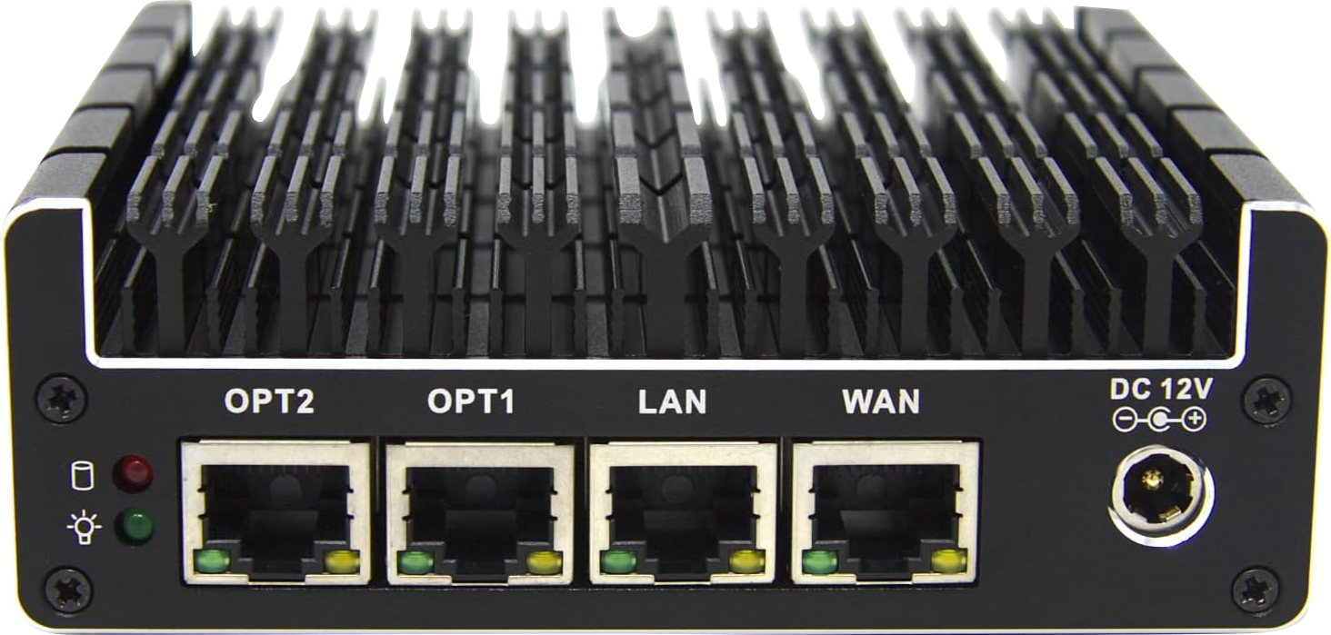 Figure 2: The Protectli Vault FW4B
The Protectli Vault FW4B has the following technical specifications:
- An Intel Celeron J3160 processor (4 cores, 4 threads) at 1.6GHz with a boost up to 2.24GHz. The processor also supports the AES-NI instruction set, which allow efficient hardware acceleration of AES encryption and decryption. This feature is critical for the operation of VPNs and Proxies to be hosted on the device.
- Four Intel Gigabit Ethernet NIC ports.
- Fanless design (thanks to a fully metallic case which acts as a heatsink)
- Support for on-board WLAN which at first I didn’t pay much attention to, seeing how I prefer delegating WLAN control to dedicated access points downstream from the router. However, the WLAN support is made available by a on-board Wi-Fi mPCI expansion slot. It turns out, this mPCI expansion slot can also be used for other purposes such as attaching a cellular 4G LTE modem card4. This can be a great addition to my router, allowing for possible fallback on cellular in case of intermittent issues with my Cable Internet.
- 2x HDMI, and 2x USB 3.2 Gen2 Type A ports: which is good to have though not very relevant to my intended usecase.
- A Serial Console RS232 via RJ-45 port: which can be cool to check out down the road, though it also is not of particular relevance to me.
Additionally, because it is a mini-computer, RAM and storage are (to a certain extent) completely configurable. The device supports SODIMM DDR3 memory, and has a mSATA connector to be used by storage devices. The device is sold in multiple memory and storage configurations. However, for my purchase, I picked the barebone configuration which is delivered without any RAM nor storage, opting to purchase those on my own. I was thus able to make sure my memory choice was from a reputable manufacturer (Crucial), and went for the highest supported amount of memory which is 8GB. Although 8GB might sound like quite a low amount, considering the device is meant to be used for a home network, and that it only supports Gigabit networking I don’t think that will be a bottleneck. Moreover, I believe the Vodafone Station I am moving away from uses 4x 256MB memory chips, allowing for a total of 1GB of addressable memory5, so this is still a big upgrade. Finally, for the storage I went with a 128GB SSD which too will be more than enough.
Managed switch
The router introduced in the previous section has exactly four ports. With one port being taken for WAN access (i.e. connected to the modem), this leaves me with only three ports to be used for devices connected downstream of my router. Because I plan to connect more than three devices to my network, I would need an additional switch which offers more ports to be connected downstream from my router, and to which all my devices would be connected. The list of requirements for such a switch is quite short:
- Number of ports: Doing a quick census of devices I would like to connect through wire, I ended up with a total of 8 devices. Since I expect this number to rise in the future, I figured a 16-port switch would be a safe bet, that would leave room for future expansion.
- Bandwidth: Because my ISP’s up-stream link has a maximum bandwidth of
1Gbps, I thought aiming for the same bandwidth for my home’s network would be reasonable, and to some extent it is. However, I now realize it would have been interesting to aim for a much higher bandwidth, seeing as hardware for2.5Gbpsand10Gbpsis becoming more accessible for hobbyist, and how nothing stops my home network from having a higher bandwidth than my ISP’s upstream link. Of course, such hardware still comes at a premium, and incurs more energy consumption, so I am not too beat about it, and I think that for a first homelab,1Gbpsis still alright. - VLAN support: This is probably the most important of all three requirements. Having VLAN support, allows to segment the switch into different virtual LANs, which behave as physically separate LANs, and can be configured as such. This allows to physically separate devices in the network even when they are connected to the same switch. Furthermore, it is possible to assign these VLANs to different networks, using different subnets, making it possible to create routing and traffic filtering rules in order to control the traffic flow between the different VLANs. Switches which offer VLAN support are referred to as “Managed switches”, those who don’t are “Unmanaged switches”.
After spending some time looking for devices fulfilling the short list of requirements above, I ended up settling on the TP-Link TL-SG116E.
 Figure 3: The TP-Link TL-SG116E
Wireless Access Points
As mentioned in the router Section, it is much better to delegate wireless access management to specialized hardware, rather than burdening the router with it. As such, the last device I still needed in order to complete my home network was a wireless access point.
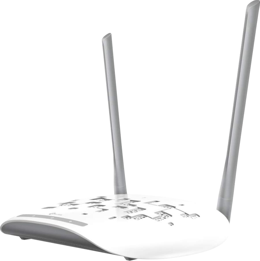 Figure 4: The TP-Link TL-WA801ND
I already own an old TL-WA801ND access point, which uses the 2.4GHzfrequency bands. My intent was to connect this access point to my IoT VLAN and use it exclusively for these devices. My reasoning might be flawed, but seeing as a lot of IoT devices rely on limited embedded hardware, my expectation was that they would probably make use of the 2.4GHz rather than 5GHz. As it stands, the only IoT devices in my network at the time were my Smart TVs, though I have plans to expand that list with other IoT devices including a couple security cameras. The operation of these devices is presumably very bandwidth intensive (considering it amounts to video down- and up- loading, respectively), as such, I figured it would improve my network’s performance to seclude these devices to the 2.4GHz bands, and reserve the 5GHz bands for “main-devices” i.e. laptops, phones, tablets, etc.
I would like to supplement my existing “IoT access point” (the TL-WA801ND) with an additional access point which I would use for the remainder of my devices. The list of requirement for such a device was short:
5GHzsupport: As mentioned above, this would allow me to use separate channels for my “main devices” from those used by my noisy and bandwidth intensive IoT devices. Additionally,5GHzwaves have a lesser penetrability of physical obstacles when compared to2.4GHz6. I realize this is not a security feature, yet it still helps me sleep better at night knowing that my access point’s broadcasts do not reach all my neighbors.- VLAN-support: Because I would like to have multiple VLANs on my network, this feature is a must on my prospective device. Without VLAN-support, implementing multiple Wireless network belonging to separate VLANs would require a separate access-point per VLAN, and would consume one port per VLAN off my switch. My
2.4GHzaccess-point also offers VLAN support, though like I said, I plan to only run a single wireless network off of it. - Power over Ethernet (PoE): This is a nice quality of life feature that would allow me to hang my access-point wherever, without having to worry about the presence of a nearby electrical socket. My
2.4GHzaccess-point also offers PoE support.
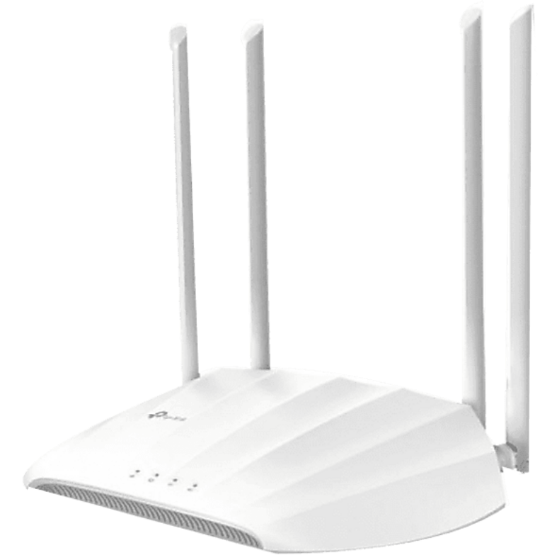 Figure 5: The TP-Link TL-WA1201
After a short search I quickly settled on the TP-Link TL-WA1201. This is a relatively cheap device, supporting all of the requirements mentioned above. It offers support for both 2.4GHz and 5GHz and boasts a theoretical maximum throughput of 1200Mbps. It should be noted that this theoretical value is calculated when both 2.4GHz and 5GHz are used, the maximum reachable bandwidth when using only the 5GHz band (as is my plan) is ~800Mbps which should be more than enough for my intended use.
Putting it all together
I broke the task of assembling and configuring all of the devices above into multiple smaller and simpler tasks. I started by first installing OPNSense on the router, and exploring some of the options available through its GUI. During this first period of trials, the router’s WAN interface was connected to my ISP router, and had an internal private address instead of a public one. This allowed me to freely tinker, without fear of taking down my home network. I then tried to create a simpler version of my goal network setup, still behind my ISP router. For this, I used a smaller (and cheaper) 5-port version of the managed switch mentioned in the previous Section, and made use only of the IoT access point. Only once I managed to get it all working in such a minimalistic setup did I move to purchase the 16-port switch and main wireless access point.
In setting up the architecture of my network, and configuring OPNSense to achieve this, I mainly followed the HomeNetworkGuy’s excellent Set Up a Fully Functioning Home Network Using OPNsense article. I was lucky enough that his setup almost exactly mirrored the one I laid for myself as a goal. If you are interested in achieving a similar setup, then I would highly recommend you read through his article, and watch the accompanying videos . I will not detail all the parameters I configured on my network, as mentioned, I simply followed the HomeNetworkGuy’s instructions, with only a few deviations. However, there are a few decisions I took which I would like to dwell on in the remainder of this section.
Physical layout
Figure 6 shows the new structure of my network. At the ISP’s side of my network is the Technicolor TC 4400‑EU cable modem (introduced in a previous article) which is connected to the TV cable connector in my apartment. Downstream from the modem is the Protectli Vault router. The router is connected to the switch using three physical connections (more on that in a bit). Finally, downstream from the switch are my two access points to which most of my devices are wirelessly connected. The few devices which make use of wired connection are directly connected to the switch.
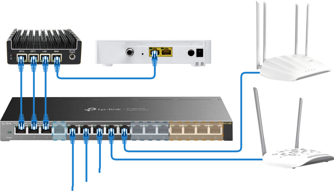 Figure 6: New network structure
Logical layout
Following TheNetworkGuy’s instructions, I arranged my network into six different sub-networks, each deployed with a separate VLAN and configured with its own IP range. Table 1 shows the configuration of these sub-networks:
| Network | VLAN ID | IPv4 range | IPv6 prefix ID |
|---|---|---|---|
| LAN | - | 192.168.1.1/24 | 0x0000 |
| Primary | 10 | 192.168.10.1/24 | 0x0001 |
| Secondary | 20 | 192.168.20.1/24 | 0x0002 |
| Services | 30 | 192.168.30.1/24 | 0x0003 |
| IoT | 40 | 192.168.40.1/24 | 0x0004 |
| Guests | 50 | 192.168.50.1/24 | 0x0005 |
The intended use of the VLANs and sub-nets above is as follows:
- LAN: meant only for management tasks. The goal is to make the management interfaces for all my network devices only available on this network for additional security.
- Primary and Secondary: These are meant for my “main” devices. There is no explicit reason why I am using two of these, one would have been enough, but I thought two would allow for more reliability.
- Services: Where all my self-hosted services will live.
- IoT: As mentioned before is meant for my IoT devices.
- Guests: Meant for guests, so that they can be given controlled access to the Internet.
I followed TheNetworkGuy’s recommendation of using IPv4 sub-net prefixes which match the VLAN IDs used for the different subnets, making it easy to immediately recognize the VLAN a device belongs to from the IP address it received fro OPNSense. I followed a similar approach for IPv6, though in this case, it is the IPv6 prefix ID which reflects the VLAN ID.
Management LAN
One great recommendation that I took from TheHomeNetworkGuy’s guide was the use of a separate LAN for management tasks. This approach relies on creating a separate LAN and restricting access to the management web-interfaces of the network equipment to be possible only from within this LAN. All users on the network would by default be assigned to other VLANs, and only when connected to this management LAN would they have access to the management web-interfaces. Though it might seem not very relevant for a home setup, I thought this was a great security feature to implement, especially considering the existence of wireless networks, and of the Guests sub‑network in my deployment. This approach is all-the-more relevant when it comes to my consumer network equipment (i.e. my switch and wireless APs), which in contrast to OPNSense do not (out of the box) give the option to limit access to their web portals to specific interfaces.
I achieved this segregation of the management interfaces using the following steps:
- On OPNSense I created a
LANinterface an assigned it to theLANport of my router. I then assigned it the IPv4 network range192.168.1.1/24, the goal being that all my network devices will receive IP addresses in this range. - I attached the switch to the router using the
LANport (In Figure 6 this is the third Ethernet cable from the left connecting both devices). Following this, my switch received an IP address in the above-configured range, and I was able to connect to its web interface and start configuring it. - Initially the switch used a default VLAN ID of
1for all its ports. These ports were also configured as untagged. This default VLAN ID is the one I will be using for my management LAN. As such, using the switch’s web interface, I have removed all other ports of the switch from this VLAN with the exception of the following ports (the numbering of the ports matches that of Figure 6 when counting from left to right):- Port 3: used to connect the switch to the router, this allows my switch to stay in the management LAN.
- Port 4: which I plan to connect to with a laptop in case I need to perform management tasks on my network.
- Ports 8 and 9: which I will be using to connect the access points. This would allow these devices to connect to the management LAN, and obtain IP addresses within its range.
- From this point on, I configured the remaining ports on my switch by adding them to the other VLANs as needed. As an example, in Figure 6, ports 5, 6, and 7 have VLAN IDs
10,40, and50respectively, because they are meant to belong to networksPrimary,IoT, andGuestsrespectively. Finally, ports 13 to 16 have VLAN ID30because they belong theServicesVLAN. Because all of these ports are meant for (non-VLAN aware) end-devices, they were all configured as untagged for their respective VLANs. - When it came time to configure the networks to be used by my access points, I first tagged the ports used to connect the access points to my switch with the corresponding VLAN IDs. In the case of the port used for my main access point, I tagged it with the VLAN IDs
10,20, and50since it will be used to access thePrimary,Secondary, andGuestsVLANs. In the case of the IoT access point, its port is only tagged with ID40which corresponds to theIoTVLAN. Finally, I configured both access points in multi-SSID mode, making sure to set the VLAN IDs for their WLANs to match those used by the corresponding VLAN on my main switch.
Please note that with the configuration above, the LAN link between the switch and the router will only be used for management traffic (which is the goal). Traffic from the other VLANs however will not be forwarded between the two devices through this link. In order to achieve this, an additional channel is used, the details of which are what the next section is about.
Link Aggregation trunk
As shown in Figure 6, the router is connected downstream to the switch through three physical connections. Two of these connections are configured as a Link Aggregation channel, meaning they are bundled to act as a single channel between the two devices. The combined channel has the combined throughput of both aggregated physical channel (2Gbps in this case). The aggregated channel also allows for additional redundancy in case of the failure of the physical channels or interface.
There are multiple protocols which can be used for the aggregated channel. These protocols can generally be classified into two categories:
- Static: Where the aggregation is set once by the network administrator on the devices sitting at both ends of the channel. Example of such algorithms include roundrobin, loadbalancing, and failover.
- Dynamic: This mainly refers to the Link Aggregation Control Protocol (LACP), which, when supported, allows the devices on both ends of the channel to negotiate how the aggregation channel needs to be setup.
LACP offers the advantage of letting the devices which will be connected through the aggregation channel handle the configuration of the channel. This avoids the situation where the channel is manually configured, but the configuration is not supported by the end-devices. Dynamic link aggregation configuration also allows for dynamic failover, in-case one of the links fails7. For these reasons, if your switch supports LACP, you should make use of it (OPNSense offers support for LACP8). However, because my switch does not support LACP, I opted for a static loadbalancing configuration. In this configuration, OPNSense balances outgoing packets between the links making up the aggregation channel, and uses a hash of the Ethernet header to do so. On the switch’s side, I only configured both ports to be used as a LAG, and did not have the option to specify the algorithm to use for the channel, so I am not exactly sure how my switch handles the channel.
Setting up a LAG channel for the “trunk” between my router and switch allows me to achieve a higher bandwidth on my network. Additionally, I figured this was the best use of the OPT1 and OPT2 interfaces available on my 4-port router (In Figure 6, these are the first two ports on my router from the left). Finally, on the switch’s side, both ports used for the Link Aggregation channel are configured as “tagged” for all VLAN IDs to allow the flow of their traffic towards the router.
Assigning unused ports to an unused VLAN
The last group of ports highlighted on the switch in Figure 6 which I haven’t covered yet is the Unused group (ports 10 to 12). This is not an additional VLAN per-say, rather, just a grouping of ports I haven’t figured out a use for yet. The following questions arise then: How should these ports be configured? And to which VLAN (if any) should they be assigned? Here too, TheHomeNetworkGuy’s guide comes in with a great recommendation: Creating an additional VLAN with an unused ID on the switch, and assigning these ports to said VLAN. This is another security measure which is common and makes more sense in a professional environment, but I still wanted to implement it in my setup. In my case, on my switch’s web interface, I created a new VLAN Unused with ID 99, and assigned all unused ports to it (untagged). Because this VLAN is only set on these ports, any devices connected to these ports will be isolated from the rest of my network devices. Furthermore, because this VLAN ID is not set on any of the ports connected to my router, my router is not connected to this VLAN, meaning devices connected to these ports won’t even receive an IP address (at least not an IPv4).
Extra credits: making it all look nice
This final section in the article is about physically laying out the different components that now make up my new home network. As a reference, Figure 7 shows a photo of my initial home network prior to setting off on this journey (you might recognize some of the devices in the photo if you have read my previous articles under the Network Organization category).
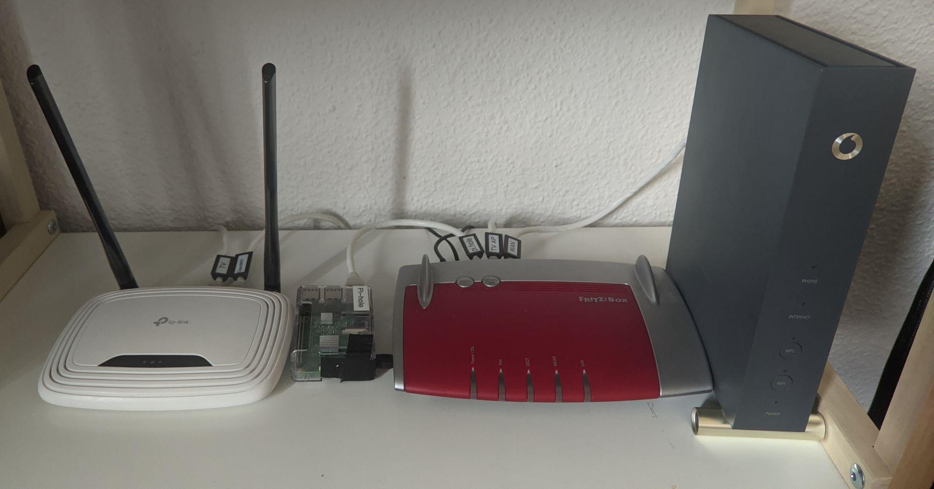 Figure 7: Home network (starting point)
As you can see, my main focus was function over form, which is okay since I anyhow didn’t have any fancy hardware to show off. Now with the deployment of the devices described throughout this article, I had more motivation to figure out a nice way to organize my network equipment, and perhaps by the same occasion show off the hard work that went into setting it all up.
It just so happened that two years ago, I got myself a 3D printer because I wanted to get into the hobby (the faithful readers, will remember that one of the motivations behind My first computer build was to have a machine performant enough for 3D modeling). This was a golden opportunity to make full use of my printer, and make myself something truly bespoke.
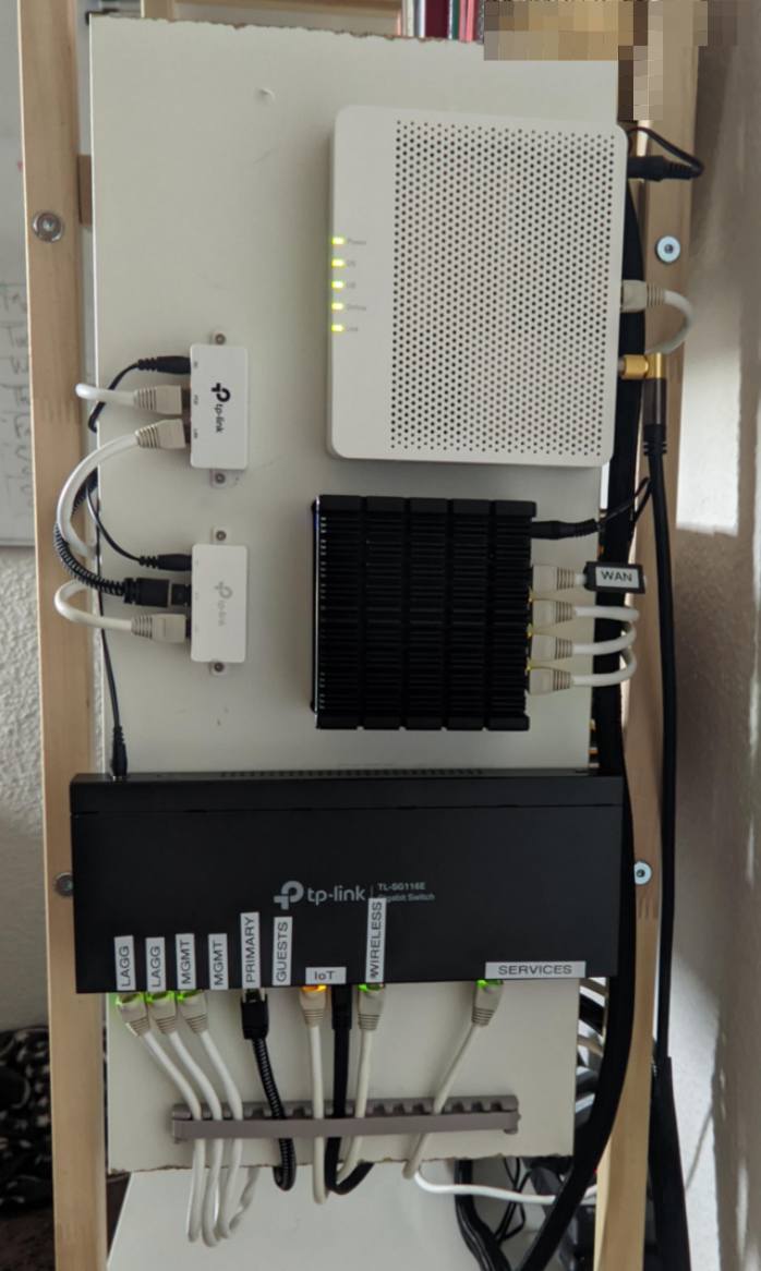 Figure 8: First attempt at a wall mount network display
The first idea I had in mind was to mount all the devices on some sort of a board, and hang that on the side of my bookcase. For this purpose, I used a Particleboard plank which was left from an old IKEA bookcase I had recycled into something else. I 3D printed a bunch of Ethernet cable holders (using designs I readily found online), and made custom supports to hang the plank itself on the side of my bookcase. Mounting the different components on the board was easy since it only required drilling the board at the correct positions and using the devices’ readily existing mounting holes.
Figure 8 shows the “intermediate” result. I say “intermediate” because the plan was to hang a Plexiglas panel on top of the wooden plank (with some spacers between the two) in order to give the stand a nice “vitrine” look. Unfortunately, after mounting all the equipment on the wooden board, it took me one look to realize that the final result was far from the vision I had in mind, and I simply didn’t like the way everything looked. Additionally, because of the way the cables needed to be routed on the back of the wooden board (not shown here), the whole setup was very rigid, and would not lend itself to recurrent disassembly (e.g. when maintenance would be needed), so back to the drawing board it was.
I based my second attempt on a RostaP’s famous honey comb wall storage design. I had previously printed and used this design for hanging other kinds of accessories to walls, and I figured its modularity and flexibility would come in handy in building what I had in mind. The model relies on a honeycomb-style base which is to be affixed to a wall, and to which different attachments are to be clipped, with a multitude of attachments for all kinds of purposes available online. The honeycomb base is modular and multiple instances of the base can be attached to each other to cover any surface. My idea was to use the bases as shelves in some kind of a “mini-network-rack”, attaching two instances side by side for each level of the rack. Before I detail the pieces I had to design, Figure 9 showcases the fully built new “mini-network rack”.
 Figure 9: New home network rack front (left) and back (right)”
Needless to say that I am very satisfied with the result. As the design of the honeycomb base is readily available, I only needed to design a few additional pieces:
 Figure 10: Shelves’ spacers design
- Spacers/supports: these are the beam-like pegs I used as support of the whole structure. Their design is very simple and they are made to be stackable. I designed three variants with the respective heights of
3cm,4cm, and5cm. The shortest of the pegs is used as the “feet” of the rack. The pegs are meant to fit into the hollow fasteners (defined in the honeycomb storage project)
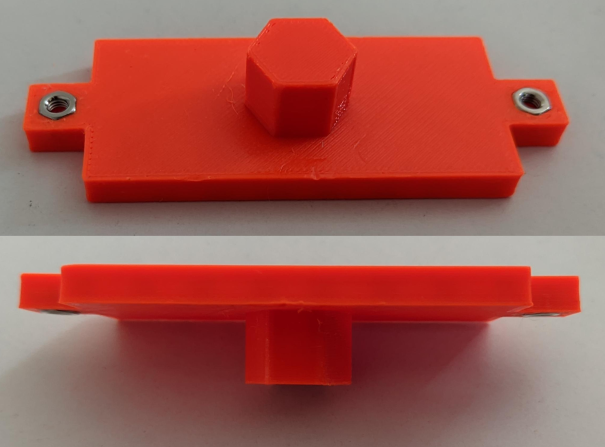 Figure 11: PoE injectors support
- PoE injectors support: Meant to hold the PoE power injectors of my access points (which allow me to power the APs using only their Ethernet cable). The injectors of both APs are the same size so the same design could be used for both. The design includes pockets which can fit
M3nuts, that can be used along with matching screws to affix the injectors to the support using the mounting holes they readily have on the sides. In the right side of Figure 9, which shows the back side of the network rack, you can see the PoE supports mounted upside-down on the top of the middle section.
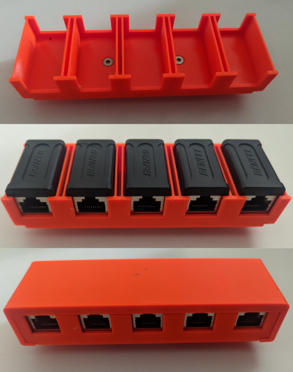 Figure 12: DIY patch panel support
- DIY patch-panel support: I wanted to have my switch positioned within the rack with its ports facing towards the front of the rack. However, this would have meant having Ethernet cables (which are coming into the rack from its back side) wrapping around the rack in order to terminate in its front (where the switch’s ports are). In addition to this not being pretty, it would have made the whole design very inflexible.
In order to remedy this, I designed a very crude patch panel, using RJ45 coupling connectors I got off Amazon, for which I designed a simple housing with two pegs that would fit into the honeycomb design’s fasteners. According to the Amazon listing, the couplers are rated up to CAT7, which would allow for up to10Gbpsspeeds. As I don’t have any10Gbpsequipment I couldn’t check that claim, though a simple speed test using some of my (1Gbps) equipment connected through one of these couplers didn’t show any degradation in speed, so I assume they are good enough for my intended purpose.
Figure 12 shows the final result. The “patch panel” is 5 ports wide, and I made two of it for a total of 10 ports (considering the width of the rack I couldn’t have made the panel larger). A total of 10 ports is exactly enough for me though, considering that out of the 16 ports of my switch, three go the router, two to the AP’s PoE injectors, and one is left for management. In the right side of Figure 9, you can see the two patch panels mounted upside-down on the lowest level on the back side of the network rack. Finally, short cable runs link the patch panel to the switch. These are the cables visible on the front of the rack on the left side of Figure 9.
 Figure 13: Ethernet combs design
- Simple Ethernet combs: Finally, I designed some very simple Ethernet combs because the ones I found online were not tight enough for my cables.
The honeycomb rack allows for a total usable internal surface of 31cm x 20cm which is more than most 3D-printable rack designs I could find online, without stepping into the 19-inch sized racks (and bigger).
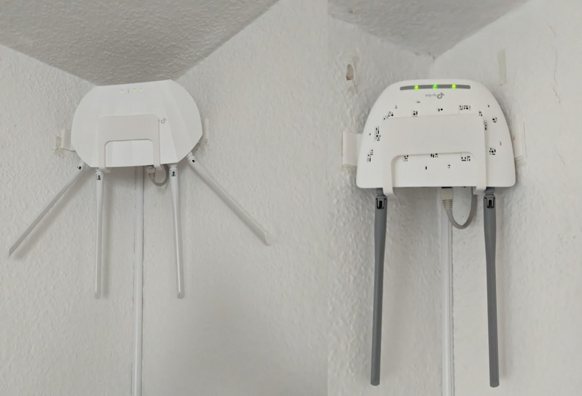 Figure 14: Access points on wall-corner brackets
Finally, for optimal Wi-Fi coverage around the house, I designed some brackets to hang my access points on the corner of different rooms. Figure 14 shows the access points mounted on the brackets and hanging on the corners of my walls. I have made all the designs above available under my Printables profile, so make sure to check it out if you are interested in reproducing something similar to my setup.
Conclusions
There is a lot I could say in conclusion to this article, but yet again, I find myself with a write-up on my hands that ended up being way longer than I originally anticipated, so I will try to make it short.
First of all, this article was not easy to finish, and it remained stuck in draft for almost half a year. The main reason for this is the breadth of topics that the project involved: Hardware, software, networking and even some 3D-design at the end. This brings me to the second point I would like to mention: I had to leave a lot out of this article. Although it is true that I relied on TheNetworkGuy’s guide for setting up OPNSense, and configuring my switch and AP I did need to deviate from his guide in a few instances (which only makes sense). In previous drafts of this article, I attempted to cover these differences, and give more details regarding my setup (e.g. DHCP and DNS configuration, firewall rules). However, these drafts ended up going nowhere, being both longer due to all the additional explanations they included, and yet seemingly always skipping some details possibly leading readers to confusion. As such, I opted to simply skip all the extra specific details, and hope to better cover them in future dedicated articles.
Another aspect which I did not cover at all here is IPv6 configuration. Although it was covered in the guide I followed, the actual configuration to be used depends a lot on your ISP, and in my case, I did have to do some research regarding Vodafone’s IPv6 network prefix length. Since that specific topic might be more interesting to more people than what I covered here, I decided to leave it to its own separate future article.
Regarding the article itself: Throughout the work described here, I feel as if I have finally reached a milestone in my home network journey. Breaking up my Vodafone station into multiple single-purpose devices has improved the overall performance of my network, and helped me improve my network knowledge in the process. One specific point of improvement on my network is the Wi-Fi quality, which no longer suffers from the intermittent disconnections my Vodafone Station was regularly subjecting me to.
Finally, OPNSense being up and running as my network’s router opens the door to so many future possibilities for me: I can setup VPN connections on the router level tunneling the traffic of specific devices on my home network to specific remote end-points. I can setup a VPN server on my home network, thus gaining the possibility to reach it (and any locally self-hosted service) from anywhere in the world. I can create custom firewall rules, hijack DNS traffic and completely isolate specific devices. So many possibilities, so many potential future projects, and hopefully just as many future articles!
